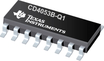

CD4053B-Q1是TI公司的一款模拟多路复用器/多路解复用器产品,CD4053B-Q1是具有逻辑电平转换的汽车类 CMOS 三路 2 通道模拟多路复用器/多路解复用器,本页介绍了CD4053B-Q1的产品说明、应用、特性等,并给出了与CD4053B-Q1相关的TI元器件型号供参考。
CD4053B-Q1 - 具有逻辑电平转换的汽车类 CMOS 三路 2 通道模拟多路复用器/多路解复用器 - 模拟多路复用器/多路解复用器 - 多路复用器/多路解复用器(Mux/Demux) - TI公司(Texas Instruments,德州仪器)
The CD4051B, CD4052B, and CD4053B analog multiplexers are digitally-controlled analog switches that have low ON impedance and very low OFF leakage current. Control of analog signals up to 20 VP-P can be achieved by digital signal amplitudes of 4.5 V to 20 V (If VDD - VSS = 3 V, a VDD - VEE of up to 13 V can be controlled; for VDD - VEE level differences above 13 V, a VDD - VSS of at least 4.5 V is required). For example, if VDD = 4.5 V, VSS = 0 V, and VEE = –13.5 V, analog signals from –13.5 V to 4.5 V can be controlled by digital inputs of 0 V to 5 V. These multiplexer circuits dissipate extremely low quiescent power over the full VDD - VSS and VDD - VEE supply-voltage ranges, independent of the logic state of the control signals. When a logic high (H) is present at the inhibit (INH) input, all channels are off.
The CD4051B is a single eight-channel multiplexer that has three binary control inputs (A, B, and C) and an inhibit input. The three binary signals select one of eight channels to be turned on and connect one of the eight inputs to the output.
The CD4052B is a differential four-channel multiplexer that has two binary control inputs (A and B) and an inhibit input. The two binary input signals select one of four pairs of channels to be turned on and connect the analog inputs to the outputs.
The CD4053B is a triple two-channel multiplexer with three separate digital control inputs (A, B, and C) and an inhibit input. Each control input selects one of a pair of channels, which are connected in a single-pole, double-throw configuration.
When these devices are used as demultiplexers, the CHANNEL IN/OUT terminals are the outputs, and the common (COM OUT/IN) terminals are the inputs.
- Qualified for Automotive Applications
- Wide Range of Digital and Analog Signal Levels
- Digital: 3 V to 20 V
- Analog: ≤ 20 VP-P
- Low ON Resistance, 125 (Typ) Over 15 VP-P Signal Input Range for VDD - VEE = 18 V
- High OFF Resistance, Channel Leakage of ±100 pA (Typ) at VDD - VEE = 18 V
- Logic-Level Conversion for Digital Addressing Signals of 3 V to 20 V (VDD - VSS = 3 V to 20 V) to Switch Analog Signals to 20 VP-P (VDD - VEE = 20 V)
- Matched Switching Characteristics, ron = 5 (Typ) for VDD - VEE = 15 V
- Very Low Quiescent Power Dissipation Under All Digital-Control Input and Supply Conditions, 0.2 µW (Typ) at VDD - VSS = VDD - VEE = 10 V
- Binary Address Decoding on Chip
- 5-V, 10-V, and 15-V Parametric Ratings
- 100% Tested for Quiescent Current at 20 V
- Maximum Input Current of 1µA at 18 V Over Full Package Temperature Range, 100 nA at 18 V and 25°C
- Break-Before-Make Switching Eliminates Channel Overlap
- Applications
- Analog and Digital Multiplexing and Demultiplexing
- Analog-to-Digital (A/D) and Digital-to-Analog (D/A) Conversion
- Signal Gating


