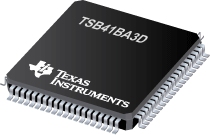

TSB41BA3D是TI公司的一款1394物理层控制器产品,TSB41BA3D是支持 S400 和 1394b 物理层 (Phy),本页介绍了TSB41BA3D的产品说明、应用、特性等,并给出了与TSB41BA3D相关的TI元器件型号供参考。
TSB41BA3D - 支持 S400 和 1394b 物理层 (Phy) - 1394物理层控制器 - 1394 - TI公司(Texas Instruments,德州仪器)
- Fully Supports Provisions of IEEE 1394b-2002 at S100, S100B, S200, S200B, S400, and S400B Signaling Rates (B Signifies IEEE 1394b Signaling)
- Fully Supports Provisions of IEEE 1394a-2000 and 1394-1995 Standards for High-Performance Serial Bus
- Fully Interoperable With Firewire™, DTVLink, SB1394, DishWire, and i.LINK™ Implementation of IEEE Std 1394
- Provides Three Fully Backward-Compatible, (1394a-2000 Fully Compliant) Bilingual 1394b Cable Ports at 400 Megabits per Second (Mbps)
- Same Three Fully Backward-Compatible Ports Are 1394a-2000 Fully Compliant Cable Ports at 100/200/400 Mbps
- Full 1394a-2000 Support Includes:
- Connection Debounce
- Arbitrated Short Reset
- Multispeed Concatenation
- Arbitration Acceleration
- Fly-By Concatenation
- Port Disable/Suspend/Resume
- Extended Resume Signaling for Compatibility With Legacy DV Devices
- Power-Down Features to Conserve Energy in Battery-Powered Applications
- Low-Power Automotive Sleep Mode Support
- Fully Compliant With Open Host Controller Interface (OHCI) Requirements
- Cable Power Presence Monitoring
- Cable Ports Monitor Line Conditions for Active Connection to Remote Node
- Register Bits Give Software Control of Contender Bit, Power Class Bits, Link Active Control Bit, and 1394a-2000 Features
- Interface to Link-Layer Controller Supports Low-Cost TI Bus-Holder Isolation
- Data Interface to Link-Layer Controller Terminal-Selectable From 1394a-2000 Mode (2/4/8 Parallel Bits at 49.152 MHz) or 1394b Mode (Eight Parallel Bits at 98.304 MHz)
- Interoperable With Link-Layer Controllers Using 3.3-V Supplies
- Interoperable With Other 1394 Physical Layers (PHYs) Using 1.8-V, 3.3-V, and 5-V Supplies
- Low-Cost 49.152-MHz Crystal Provides Transmit and Receive Data at 100/200/400 Mbps and Link-Layer Controller Clock at 49.152 MHz and 98.304 MHz
- Separate Bias (TPBIAS) for Each Port
- Low-Cost, High-Performance 80-Terminal TQFP (PFP) Thermally Enhanced Package
- Software Device Reset (SWR)
- Fail-Safe Circuitry Senses Sudden Loss of Power to the Device and Disables the Ports to Ensure That the TSB41BA3D Does Not Load the TPBIAS of Any Connected Device and Blocks Any Leakage From the Port Back to Power Plane
- 1394a-2000-Compliant, Common-Mode Noise Filter on the Incoming Bias Detect Circuit to Filter Out Crosstalk Noise
- Cable/Transceiver Hardware Speed and Port Mode Are Selectable by Terminal States
- Supports Connection to CAT5 Cable Transceiver by Allowing Ports to be Forced to Beta-Only, 400-Mbps-Only, 200-Mbps-Only or 100-Mbps-Only
- Supports Connection to S200 Plastic Optical Fiber Transceivers by Allowing Ports to be Forced to 1394b Beta-Only, S200-Mbps-Only, and S100-Mbps-Only
- Optical Signal Detect Input for All Ports in Beta Mode Enables Connection to Optical Transceivers
- Supports Use of 1394a Connectors by Allowing Ports 1 and 2 to Be Forced to 1394a-Only Mode
PowerPAD is a trademark of Texas Instruments. Firewire is a trademark of Apple Computer, Inc. i.LINK is a trademark of Sony Kabushiki Kaisha TA Sony Corporation. All other trademarks are the property of their respective owners.
DESCRIPTION/ORDERING INFORMATION
The TSB41BA3D provides the digital and analog transceiver functions needed to implement a three-port node in a cable-based IEEE 1394 network. Each cable port incorporates two differential line transceivers. The transceivers include circuitry to monitor the line conditions as needed for determining connection status, for initialization and arbitration, and for packet reception and transmission. The TSB41BA3D interfaces with a link-layer controller (LLC), such as the TSB82AA2, TSB12LV21, TSB12LV26, TSB12LV32, TSB42AA4, TSB42AB4, TSB12LV01B, or TSB12LV01C. It can also be connected via cable port to an integrated 1394 Link + PHY layer such as the TSB43AB2.
The TSB41BA3D is powered by a single 3.3-V supply. The core voltage supply is supplied by an internal voltage regulator to the PLLVDD-CORE and DVDD-CORE terminals. To protect the phase-locked loop (PLL) from noise, the PLLVDD-CORE terminals must be separately decoupled from the DVDD-CORE terminals. The PLLVDD-CORE terminals are decoupled with 1-µF and smaller decoupling capacitors and the DVDD-CORE terminals are separately decoupled with 1-µF and smaller decoupling capacitors. The separation between DVDD-CORE and PLLVDD-CORE must be implemented by separate power supply rails or planes.
The TSB41BA3D can be powered by dual supplies, a 3.3-V supply for I/O and a core voltage supply. The core voltage supply is supplied to the PLLVDD-CORE and DVDD-CORE terminals to the requirements in the recommended operating conditions section of this data sheet. The PLLVDD-CORE terminals must be separated from the DVDD-CORE terminals, the PLLVDD-CORE terminals are decoupled with 1-µF and smaller decoupling capacitors and the DVDD-CORE terminals separately decoupled with 1-µF and smaller decoupling capacitors. The separation between DVDD-CORE and PLLVDD-CORE can be implemented by separate power supply rails, or by a single power supply rail, where the DVDD-CORE and PLLVDD-CORE are separated by a filter network to keep noise from the PLLVDD-CORE supply.
The TSB41BA3D requires an external 49.152-MHz crystal to generate a reference clock. The external clock drives an internal PLL, which generates the required reference signal. This reference signal provides the clock signals that control transmission of the outbound encoded information. A 49.152-MHz clock signal is supplied by the PHY to the associated LLC for synchronization of the two devices and is used for resynchronization of the received data when operating the PHY-link interface in compliance with the IEEE 1394a-2000 standard. A 98.304-MHz clock signal is supplied by the PHY to the associated LLC for synchronization of the two devices when operating the PHY-link interface in compliance with the IEEE 1394b-2002 standard. The power-down (PD) function, when enabled by asserting the PD terminal high, stops operation of the PLL.
Data bits to be transmitted through the cable ports are received from the LLC on 2, 4, or 8 parallel paths (depending on the requested transmission speed and PHY-link interface mode of operation). They are latched internally, combined serially, encoded, and transmitted at 98.304, 122.78, 196.608, 245.76, 393.216, or 491.52 Mbps (referred to as S100, S100B, S200, S200B, S400, or S400B speed, respectively) as the outbound information stream.
The PHY-link interface can follow either the IEEE 1394a-2000 protocol or the IEEE 1394b-2002 protocol. When using a 1394a-2000 LLC such as the TSB12LV26, the BMODE terminal must be deasserted. The PHY-link interface then operates in accordance with the legacy 1394a-2000 standard. When using a 1394b LLC such as the TSB82AA2, the BMODE terminal must be asserted. The PHY-link interface then conforms to the 1394b-2002 standard.
The cable interface can follow either the IEEE 1394a-2000 protocol or the 1394b protocol on all ports. The mode of operation is determined by the interface capabilities of the ports being connected. When any of the three ports is connected to a 1394a-2000-compliant device, the cable interface on that port operates in the 1394a-2000 data-strobe mode at a compatible S100, S200, or S400 speed. When a bilingual port is connected to a 1394b-compliant node, the cable interface on that port operates per the 1394b-2002 standard at S100B, S200B, or S400B speed. The TSB41BA3D automatically determines the correct cable interface connection method for the bilingual ports.
NOTE: The BMODE terminal does not select the cable interface mode of operation. The BMODE terminal selects the PHY-link interface mode of operation and affects the arbitration modes on the cable. When the BMODE terminal is deasserted, the PHY-link interface is placed in 1394a-2000 mode and BOSS arbitration is disabled. When the BMODE terminal is asserted, the PHY-link interface is placed in 1394b-2002 mode and BOSS arbitration is enabled.
During packet reception, the serial data bits are split into 2-, 4-, or 8-bit parallel streams (depending on the indicated receive speed and the PHY-link interface mode of operation), resynchronized to the local system clock, and sent to the associated LLC. The received data is also transmitted (repeated) on the other connected and active cable ports.
Both the twisted pair A (TPA) and the twisted pair B (TPB) cable interfaces incorporate differential comparators to monitor the line states during initialization and arbitration when connected to a 1394a-2000-compliant device. The outputs of these comparators are used by the internal logic to determine the arbitration status. The TPA channel monitors the incoming cable common-mode voltage. The value of this common-mode voltage is used during 1394a-mode arbitration and sets the speed of the next packet transmission. In addition, the TPB channel monitors the incoming cable common-mode voltage on the TPB pair for the presence of the remotely supplied twisted pair bias (TPBIAS) voltage.
When connected to a 1394a-2000-compliant node, the TSB41BA3D provides a 1.86-V nominal bias voltage at the TPBIAS terminal for port termination. The PHY contains three independent TPBIAS circuits (one for each port). This bias voltage, when seen through a cable by a remote receiver, indicates the presence of an active connection. This bias voltage source must be stabilized by an external filter capacitor of 1 µF.
The line drivers in the TSB41BA3D are designed to work with external 112- termination resistor networks in order to match the 110- cable impedance. One termination network is required at each end of a twisted-pair cable. Each network is composed of a pair of series-connected ~56- resistors. The midpoint of the pair of resistors that is connected to the TPA terminals is connected to its corresponding TPBIAS voltage terminal. The midpoint of the pair of resistors that is directly connected to the TPB terminals is coupled to ground through a parallel RC network with recommended values of 5 k and 270 pF. The values of the external line-termination resistors are designed to meet the standard specifications when connected in parallel with the internal receiver circuits. A precision external resistor connected between the R0 and R1 terminals sets the driver output current, along with other internal operating currents.
When the power supply of the TSB41BA3D is off while the twisted-pair cables are connected, the TSB41BA3D transmitter and receiver circuitry present a high-impedance signal to the cable that does not load the device at the other end of the cable.
When the TSB41BA3D is used without one or more of the ports brought out to a connector, the twisted-pair terminals of the unused ports must be terminated for reliable operation. For each unused port, the preferred method is for the port to be forced to the 1394a-only mode (data-strobe-only mode, DS), then the TPB+ and TPB– terminals can be tied together and then pulled to ground; or the TPB+ and TPB– terminals can be connected to the suggested normal termination network. The TPA+ and TPA– terminals of an unused port can be left unconnected. The TPBIAS#_SD# terminal can be left unconnected.
If the port is left in bilingual (Bi) mode, then the TPB+ and TPB– terminals can be left unconnected or the TPB+ and TPB– terminals can be connected to the suggested normal termination network. The TPA+ and TPA– terminals of an unused port can be left unconnected. The TPBIAS#_SD# terminal can be left unconnected.
If the port is left in a forced 1394b Beta-only (B1, B2, or B4) mode, then the TPB+ and TPB– terminals can be left unconnected or the TPB+ and TPB– terminals can be connected to the suggested normal termination network. The TPA+ and TPA– terminals of an unused port can be left unconnected. The TPBIAS#_SD# terminal must be pulled to ground through a 1.2-k or smaller resistor.
To operate a port as a 1394b bilingual port, the speed/mode selections terminals (S5_LKON, S4, S3, S2_PC0, S1_PC1, and S0_PC2) need to be pulled to VCC or ground through a 1-k resistor. The port must be operated in the 1394b bilingual mode whenever a 1394b bilingual or a 1394b Beta-only connector is connected to the port. To operate the port as a 1394a-only port, the speed/mode selection terminals must be configured correctly to force 1394a-2000-only operation on that port. The only time the port must be forced to the data-strobe-only mode is if the port is connected to a 1394a connector (either 6-pin, which is recommended, or 4-pin). This mode is provided to ensure that 1394b signaling is never sent across a 1394a cable.
NOTE: A bilingual port can only connect to a 1394b-only port that operates at S400b. It cannot establish a connection to a S200b or S100b port. A port that has been forced to S400b (B4) can connect to a 1394b-only port at S400b (B4) or S200b (B2) or S100b (B1). A port that has been forced to S200b can connect to a 1394b-only port at S200b or S100b. A port that has been forced to S100b can only connect to a 1394b-only port at S100b.
The TESTM, SE, and SM terminals are used to set up various manufacturing test conditions. For normal operation, the TESTM terminal must be connected to VDD through a 1-k resistor. The SE and SM terminals must be tied to ground through a 1-k resistor.
Three package terminals are used as inputs to set the default value for three configuration status bits in the self-ID packet. They can be pulled high through a 1-k resistor or hardwired low as a function of the equipment design. In some speed/mode selections the S2_PC0, S1_PC1, and S0_PC2 terminals indicate the default power-class status for the node (the need for power from the cable or the ability to supply power to the cable); see . The contender bit in the PHY register set indicates that the node is a contender either for the isochronous resource manager (IRM) or for the bus manager (BM). On the TSB41BA3D, this bit can only be set by a write to the PHY register set. If a node is a contender for IRM or BM, then the node software must set this bit in the PHY register set.
The LPS (link power status) terminal works with the S5_LKON terminal to manage the power usage in the node. The LPS signal from the LLC is used with the LCtrl bit (see and in the APPLICATION INFORMATION section) to indicate the active/power status of the LLC. The LPS signal also resets, disables, and initializes the PHY-LLC interface (the state of the PHY-LCC interface is controlled solely by the LPS input regardless of the state of the LCtrl bit).
NOTE: The TSB41BA3D does not have a cable-not-active (CNA) terminal. To achieve a similar function, the individual PHY ports can be set up to issue interrupts whenever the port changes state. If the LPS terminal is low, then this generates a link-on (LKON) output clock. See register bits PIE, PEI, and WDIE along with the individual interrupt bits.
The LPS input is considered inactive if it remains low for more than the LPS_RESET time (see the LPS terminal definition) and is considered active otherwise. When the TSB41BA3D detects that the LPS input is inactive, the PHY-LLC interface is placed into a low-power reset state in which the CTL and D outputs are held in the logic 0 state and the LREQ input is ignored; however, the PCLK output remains active. If the LPS input remains low for more than the LPS_DISABLE time (see the LPS terminal definition), then the PHY-LLC interface is put into a low-power disabled state in which the PCLK output is also held inactive. The TSB41BA3D continues the necessary repeater functions required for normal network operation regardless of the state of the PHY-LLC interface. When the interface is in the reset or disabled state and the LPS input is again observed active, the PHY initializes the interface and returns to normal operation. The PHY-LLC interface is also held in the disabled state during hardware reset. When the LPS terminal is returned to an active state after being sensed as having entered the LPS_DISABLE time, the TSB41BA3D issues a bus reset. This broadcasts the node self-ID packet, which contains the updated L bit state (the PHY LLC now being accessible).
The PHY uses the S5_LKON terminal to notify the LLC to power up and become active. When activated, the output S5_LKON signal is a square wave. The PHY activates the S5_LKON output when the LLC is inactive and a wake-up event occurs. The LLC is considered inactive when either the LPS input is inactive, as previously described, or the LCtrl bit is cleared to 0. A wake-up event occurs when a link-on PHY packet addressed to this node is received, or conditionally when a PHY interrupt occurs. The PHY deasserts the S5_LKON output when the LLC becomes active (both LPS sensed as active and the LCtrl bit set to 1). The PHY also deasserts the S5_LKON output when a bus reset occurs, unless a PHY interrupt condition exists which would otherwise cause S5_LKON to be active. If the PHY is power-cycled and the power class is 0 through 4, then the PHY asserts S5_LKON for approximately 167 µs or until both the LPS is active and the LCtrl bit is 1.


